The GT series of mobile gravimeters combine inertial navigation systems (INS), vertical gravity sensors and global positioning systems (GPS) to measure gravity anomalies related to sub-surface geology and structure.
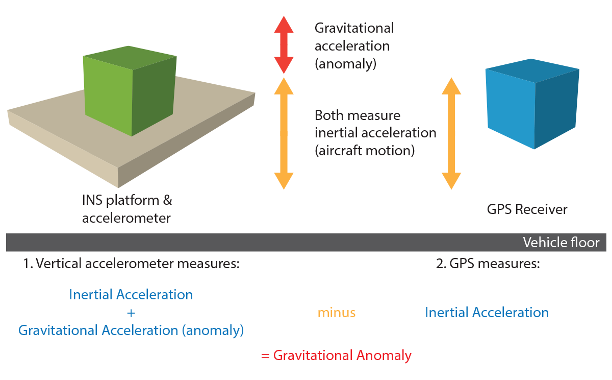
In the schematic above, the INS and vertical gravity sensor measure the inertial acceleration of the vehicle/vessel and the gravitational acceleration due to geology (gravity anomaly) while the GPS system measures the inertial acceleration of the vehicle/vessel only. By subtracting one from the other the gravity anomaly can be calculated.
GT mobile gravimeters measure very small gravity anomalies to a very high degree of accuracy, far beyond the capability of traditional zero-length spring devices.
The accuracy of the measured gravity anomalies is normally determined by analysing the differences at cross-over points from the survey data. The root mean squared (RMS) error is the statistical tool usually used, after first order levelling is applied, to determine the accuracy of the gravity data during a survey. The resolution of the gravity data along line is a function of the speed of the vehicle/vessel and the filter length applied to the data.
The GT-1A & GT-2A airborne and the GT-2M marine GPS-INS vertical scalar gravimeters are rugged, easy to install and operate, and have outstanding performance in turbulent survey conditions.
All three meters have common technology that incorporates a single vertical gravity sensor with a GPS-INS Schuler-tuned three-axis inertial platform. The gravity sensor is a custom-designed vertical gravity sensor mounted inside the gyro-stabilised platform. Inputs from fibre optic gyros, inclinometers, angle sensors and dual frequency GPS are used to drive servo motors which maintain the sensor in a vertical position. This eliminates the effects of horizontal accelerations in the measured signal. The entire assembly is mounted on a rotation table, maintaining the sensor orientation at the same heading.
Gravity data is sampled at 18.75 Hz, sub-sampled to 2 Hz and integrated with dual frequency GPS data to remove effects of vertical aircraft acceleration and Eötvös effect. Final gravity is reduced using a non-stationary adaptive Kalman filter using the raw gravity, the vertical velocity (GPS phase information), and platform misalignment errors. Filter length is user-defined according to resolution requirements.
The GT-1A, GT-2A and GT-2M are single vertical sensor, GPS-INS scalar gravimeters with Schuler-tuned three-axis inertial platforms. The technology common to all three gravimeters consists of the basic units as illustrated below.
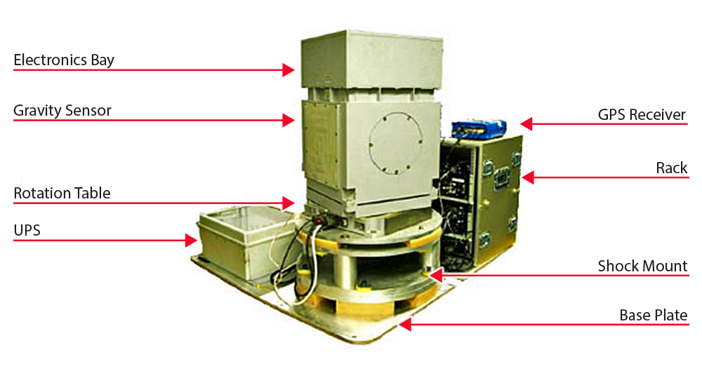
The gravity sensor and electronics bay combined weighs 50 kg and measures 40 x 40 x 60 cms high. The rotation table measures 40 x 40 x 10 cms high. The foam-based shock-mount system has a specific cut-off frequency to eliminate vibration noise and is 60 cms in diameter and 30 cms high. The overall height of the installation is 104 cms and weighs in at approximately 190 kgs when the protective restraint system is fitted. The gravity sensor is held vertically by an inertial platform and the rotation-table provides the platform’s azimuth axis.
Connections to the gravimeter are: a 27 Vdc power source drawing approximately five amps; a GPS RS-232 serial link providing data used to assist in aligning the platform vertical; and a second serial connection to any laptop or field data acquisition computer. This computer acts as the control and display unit (CDU) for the gravimeter, and also collects and stores survey data.
 The gravity sensing element (GSE) has an axial design with a reference mass on a spring suspension, a photoelectric position pickup and a moving-coil force feedback transducer. The GSE suspension design eliminates the effect of cross-coupling, an undesirable effect which contaminates gravity measurements with components of horizontal accelerations induced by aircraft motion. This feature helps the GT-1A to collect data in the presence of large horizontal accelerations, such as during periods of high turbulence.
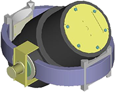
The GSE, with a bandwidth of 100 Hz, is installed on the gyro-stabilized platform contained in a double-axis gimbal suspension (ref. black cylinder above). The platform also holds two horizontal accelerometers, a dynamically tuned gyro with a vertical angular momentum and a fibre optic gyro (FOG).
The gravimeter also contains a microprocessor, input/output interfaces, and secondary power supplies, all within the electronics bay at the top of the main unit. The GSE is placed in a double-loop constant-temperature environment on the inertial platform. The other elements installed on the platform, plus the current regulator of a code-to-current converter within the gyro control circuit, are individually temperature controlled.

The gravimeter is fully automated – no operator is required on board the aircraft while collecting data on survey lines. All systems including stabilization servo systems, temperature control systems and gyroscopic correction systems are controlled by the built-in microprocessor. The computer also takes control of actuation, reference measurements, balancing, and measurements during survey mode. A vertical gyro correction system using GPS-derived information on latitude and aircraft speed provides vertical gyro stability. An optimal Kalman filter is implemented in control algorithms for both the stabilization servo system and the vertical gyro correction system.
The dynamic range for both the GT-1A and GT-2M is +/- 500 Gals (+/- 0.50 g). The GT-2A has a dynamic range of +/- 1,000 Gals (+/- 1 g). Data is acquired through short periods of GSE saturation in extreme turbulence by the automatic application of a reduced-order Kalman filter, enabling platform misalignment to be computed and hence controlled.
The internal microprocessor carries out a large number of measurement and control functions. Measurements of platform orientation, rotation rates and sensor outputs are taken at 300 Hz, the rate at which critical platform control and other internal functions are carried out. The high sampling rate eliminates aliasing of the high frequency vibrations encountered in an aircraft. This data is passed through an anti-aliasing filter and is subsequently processed at a rate of 18.75 Hz, the frequency of the main control loop. The main control loop also runs at this frequency. Velocity and latitude data from the GPS receiver provide GPS-aided platform levelling.
The gravimeter is operated by programs running on the CDU. The easy-to-use menu-based programs include calibration and diagnostic functions. The diagnostic program maintains a running check on the serviceability of all gravimeter sub-systems.
The GSE design provides for a highly linear long-term drift which is easily compensated by recording reference measurements at the same location immediately prior to and following each period of data acquisition. These reference measurements are then used to compensate data collected using linear interpolation. Four internal temperature monitors are recorded and used during post-processing to correct the GSE inherent drift to within 0.1 mGals/day.
The GT gravimeters provide a wide range of spatial resolutions through the application of filters with varying cut-off frequencies. Filters are chosen on the basis of aircraft/vessel speed, acquisition conditions and target dimensions. For airborne applications, filters might vary from 80 to 120 seconds or longer for extremely turbulent flights, which provides half-wavelength resolutions of 2.0 and 3.0 kms respectively with an aircraft ground speed of 50 m/sec. A helicopter flying at half this speed would provide resolutions of 1.0 km and 1.5 kms respectively with 80 and 120-second filters. For marine applications, filters can vary from 100 to 400 seconds which provide half-wavelength resolutions of 150m to 600m respectively with a vessel speed of 3 m/sec.
The processing software suite consists of a number of programs for in-field evaluation of the validity and quality of the raw data files collected by the gravimeter and GPS receiver. Corrections are generated, including allowance for gravimeter movement relative to the GPS antenna through shockmount distortion, platform misalignment and temperature compensation. The data, after being processed through a Kalman filter to generate free-air delta-g values in mGals, is levelled and output as free-air gravity. The final corrected values can be ready within a few hours after acquisition for assessment of data quality and follow-on survey planning.
this site and its contents are
© 2026 Canadian Micro Gravity